A Practical Case Study of Gully Erosion Control in Alibiuba, Delta State
The establishment of proposed road levels relative to existing ground conditions represents one of the most critical decisions in highway engineering. When survey pegs are positioned and elevation differentials become apparent, the implications extend far beyond simple earthwork quantities.
In the Nigerian context, characterized by lateritic soil formations, high-intensity rainfall events, and complex urban development patterns, vertical alignment design demands rigorous technical analysis balanced with practical implementation considerations.
The determination of optimal road elevations encompasses flood prevention, property access preservation, structural protection of adjacent facilities, and fiscal responsibility. Inadequate attention to these parameters becomes evident within the first operational rainy season, often necessitating costly remedial interventions.
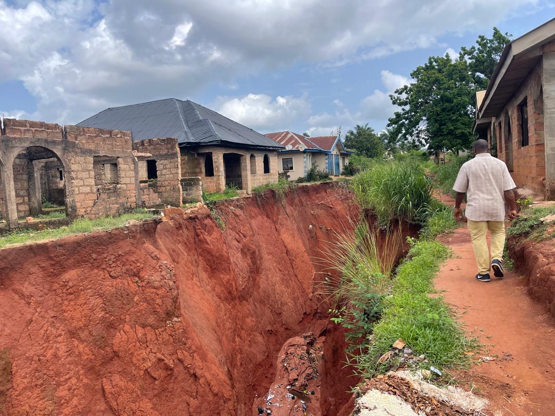
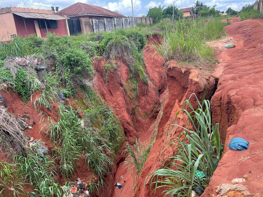
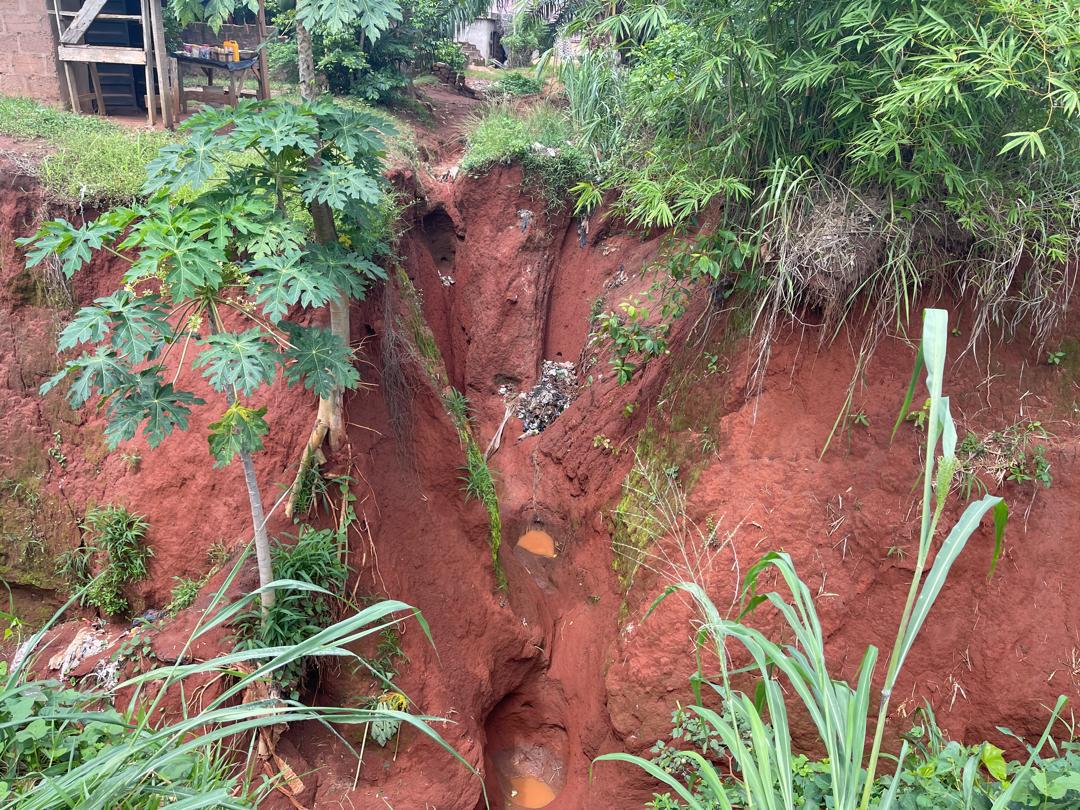
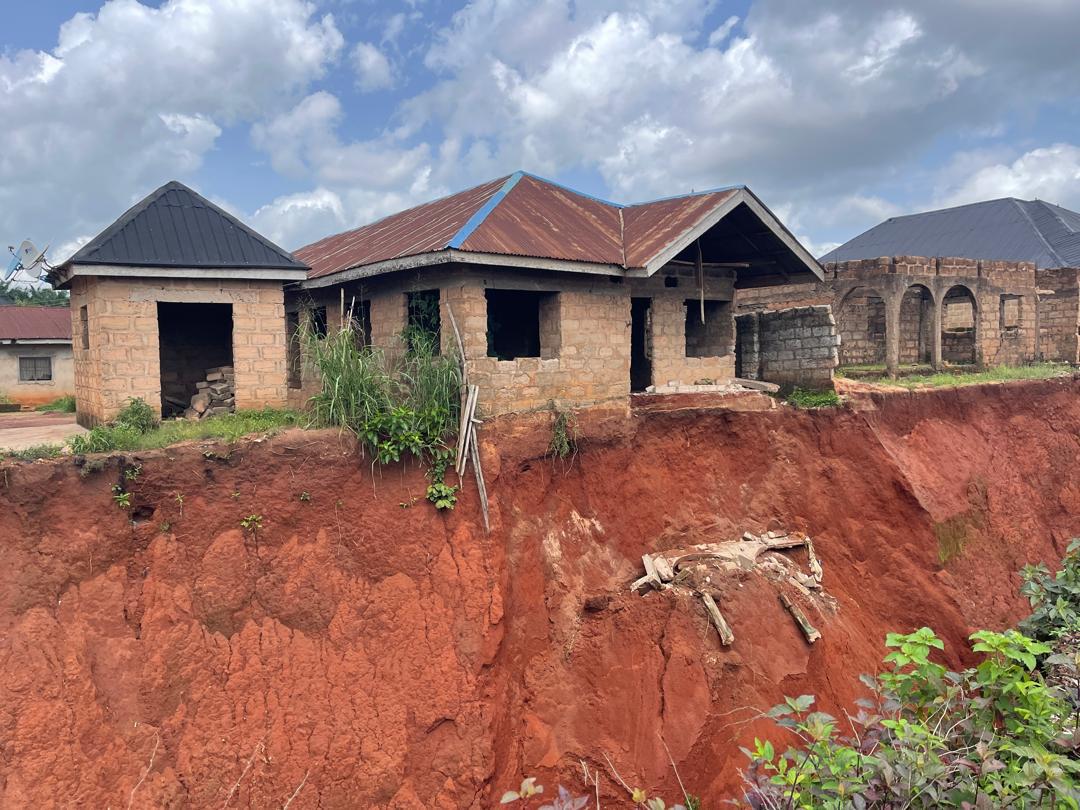
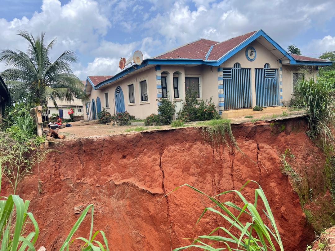
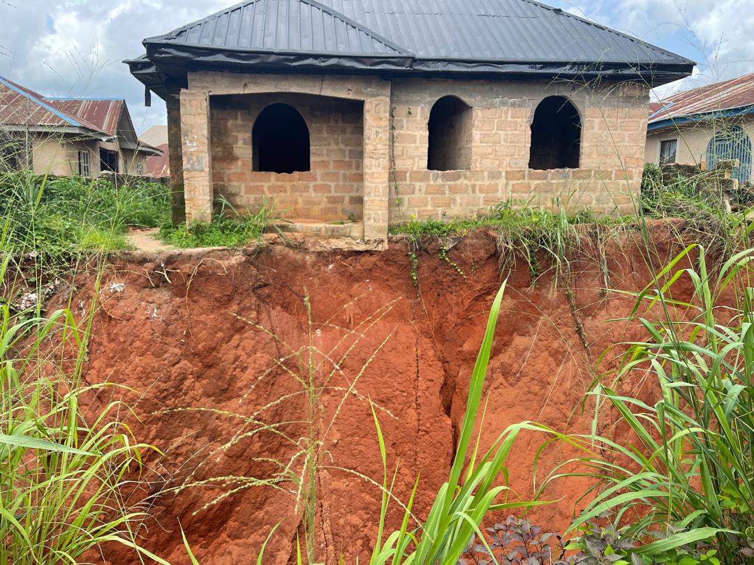
For the residents of Alibiuba Community in Ika South Local Government Area, Delta State, the gap between the Existing Ground Level (EGL) and the Proposed Ground Level (PGL) was not merely a design abstraction. It was a structural emergency. Uncontrolled stormwater runoff had carved deep, vertical channels into the red laterite, leaving residential properties perched precariously on the edge of collapsing earth.
Commissioned by the Delta State Government, Ministry of Works, JEFCON & Associates Ltd was tasked with designing and executing the Stormwater Management & Control Measures for Alibiuba Community. What follows is an analysis of how the theoretical principles of vertical alignment and earthwork optimization were practically applied to reclaim this degraded landscape, specifically focusing on the interventions along Obi Road and Enumah Road.
The EGL-PGL Dilemma: Mapping the Menace
The relationship between Existing Ground Level (EGL) and Proposed Ground Level (PGL) constitutes a fundamental design parameter. Theoretical design approaches advocate for cut-and-fill optimization to minimize earthwork import and export. However, practical application within environments suffering from severe gully erosion reveals considerable complexity.
Before a single excavator bucket hit the ground, the engineering team had to understand the geometry of the failure. The pre-intervention site conditions on Obi and Enumah Roads were severe. Uncontrolled surface runoff had carved deep, vertical channels into the red laterite, undermining residential foundations and fence lines.
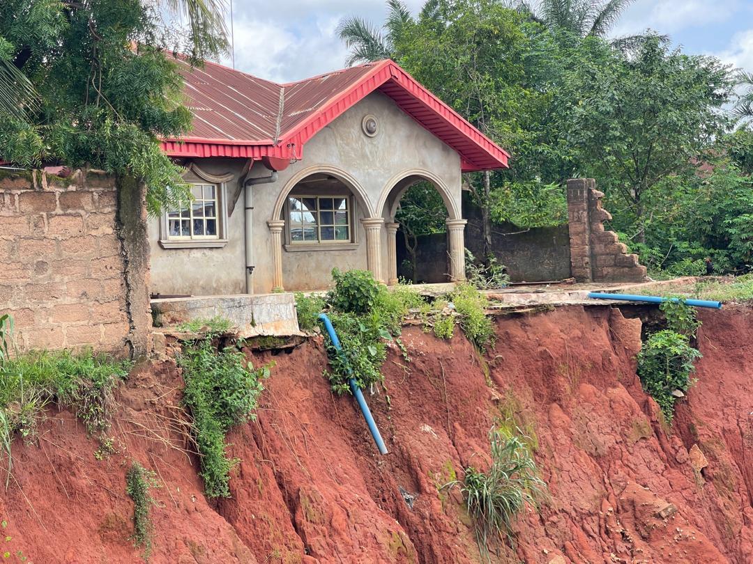
Phase 1: Pre-intervention site conditions and gully mapping. The images reveal severe gully erosion with vertical lateritic faces exposing the foundations of adjacent residential buildings. Note the proximity of occupied and under-construction structures to the active erosion channels, and the survey team assessing the depth and lateral extent of the gully.
The survey team, led by Surv. Justice U. Anyin and checked by Engr. J.C. Onwualu, had to capture a highly dynamic topography. Working within the Universal Transverse Mercator (UTM) Zone 32 coordinate system, the initial Survey Layout Map required meticulous documentation of existing drainage, flow direction arrows, spot heights, and the precise extents of the gully.
Identifying the exact chainages and integrating them with existing landmarks—like the nearby Technical College and local road networks—was critical. The design process was iterative, with the layout map undergoing several revisions between June 2022 and April 2026. This ensured that the proposed drainage and sewer lines would actually intercept the destructive flow paths identified during this initial mapping phase.
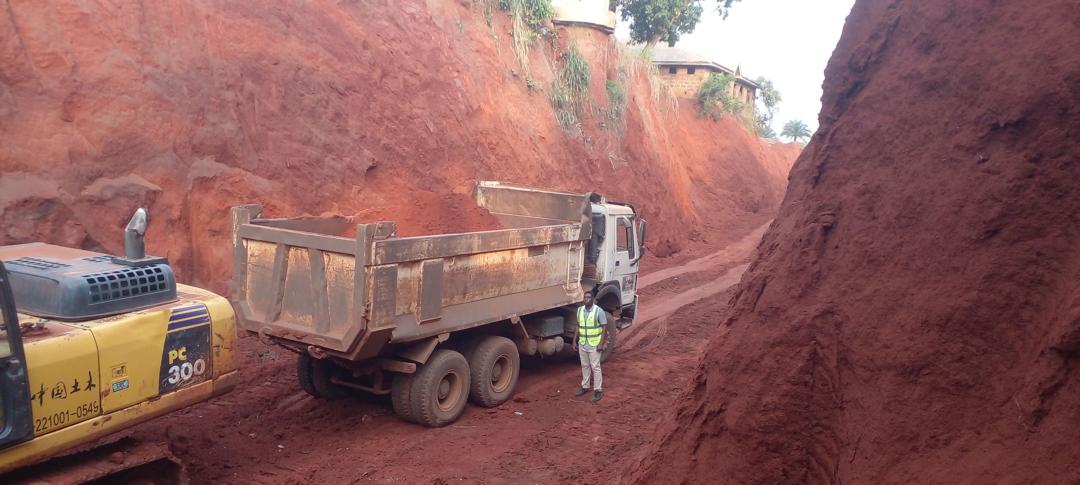
Deep excavation zone illustrating the interface between proposed road subgrade and existing compound infrastructure. Personnel establishing drainage channel alignment during lateritic material removal. The elevation differential between the road formation and adjacent properties presents access and retaining structure challenges requiring engineering resolution.
Earthwork Optimization in Confined Spaces
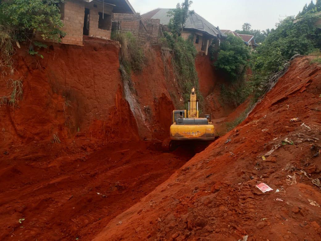
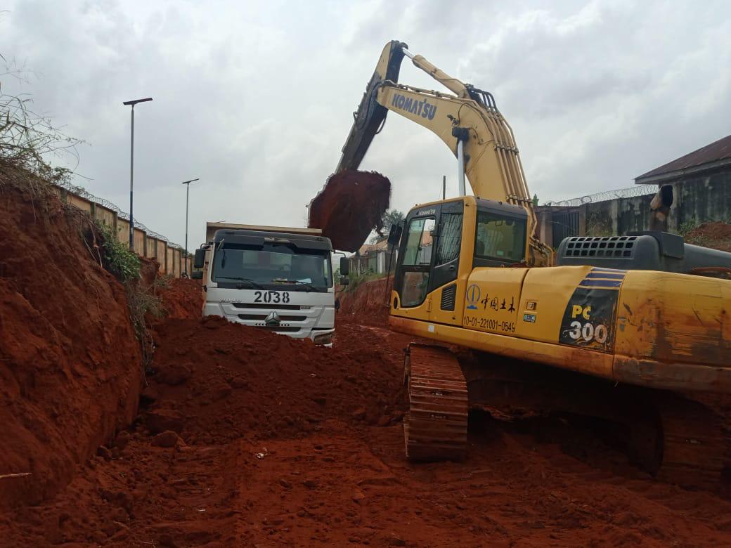
Once the design was issued for construction, the physical reality of the site dictated our methodology. Moving earth costs money, and importing fill costs more. The ideal scenario—mass haul balance—seeks to minimize waste through strategic cut-and-fill coordination. But the gullies at Alibiuba were deep, narrow, and confined.
[Figures 2a – 2e: Pictures 25, 26, 27, 28, 29, 30, 31, 32, 33, 34]
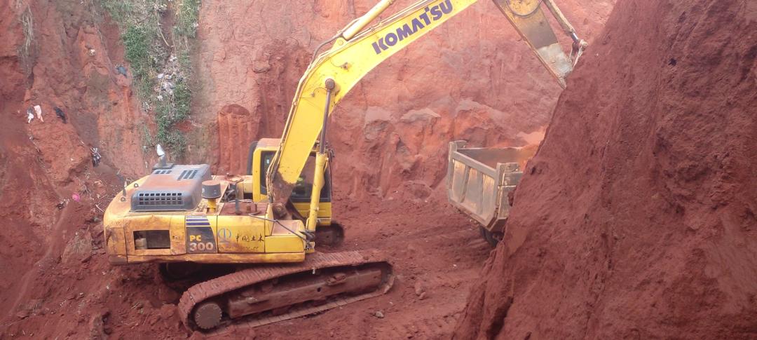
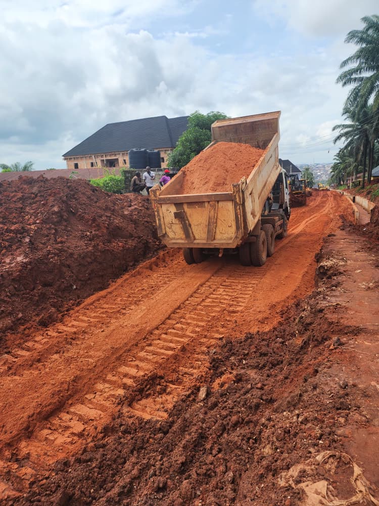
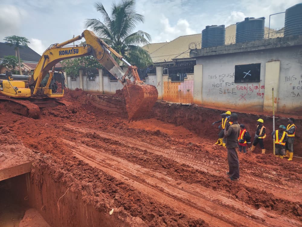
Phase 2: Heavy earthworks and gully reclamation. Komatsu PC300 excavators are deployed inside the deep gully trenches to excavate, load, and haul lateritic material. The confined space between the steep gully walls highlights the logistical complexity of the mass haul operations, while the Shantui bulldozer begins the initial leveling of the reclaimed zones.
The first step on Obi Road was the removal of unsuitable materials. In-situ laterite, especially in gully-prone areas, often exhibits high plasticity or poor moisture-density relationships. Leaving this material in the subgrade would almost certainly lead to differential settlement under traffic loads. Following this, targeted excavations commenced, such as at CH 2+025 on the Right Hand Side (RHS) of Obi Road, and further down at CH 1+800, where excavators cut the formation down to the designed subgrade level.
Operating heavy machinery in such a restricted footprint required precise coordination to avoid destabilizing the already fragile gully walls. We utilized Komatsu PC300 excavators to carefully trim the unstable vertical faces and load the excavated lateritic soil into heavy-duty dump trucks.
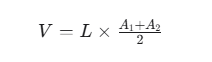
To manage the earthworks efficiently, we relied on the average end-area method for volume calculations:
Where V is the volume of earthwork, L is the distance between cross-sections, and A1 and A2 are the cross-sectional areas of the cut or fill at those stations. This allowed us to balance the mass haul, minimizing the need to import fill from external borrow pits.
Handling laterite in this environment is tricky; its moisture content fluctuates wildly, which directly impacts its shear strength and compaction characteristics. The lateritic fill material was placed in controlled loose layers—typically not exceeding 150mm to 200mm—and compacted to at least 95% of the Maximum Dry Density (MDD) determined via the Modified AASHTO Proctor test. The earthworks in this phase weren’t just about moving dirt; they were about managing the geotechnical properties of the fill material in real-time to ensure the reclaimed gully wouldn’t simply settle and reopen during the next heavy downpour.
Balancing Topography and Achieving the Subgrade
With the deep gullies filled and the bulk earthworks completed, the project transitioned into balancing the topography to achieve the Proposed Ground Level. This is where the raw earthworks are refined into a functional engineering asset, addressing the theoretical need for longitudinal gradients and cross-falls.
Phase 3: Topographical balancing and subgrade formation. The XCMG GR215 motor grader and Shantui bulldozer are shown screeding and leveling the lateritic soil. The images demonstrate the transformation of the deep erosion channel into a wide, stabilized road formation, with heavy compaction tracks visible across the subgrade.
The introduction of the XCMG GR215 motor grader allowed for precise screeding of the lateritic soil to achieve the road crown and gradient required before final compaction. Simultaneously, the excavators and dozers were used to trim and bench the side slopes. Reducing the angle of repose on these slopes was a critical geotechnical step to prevent future landslides and integrate the old gully edges with the new fill.
As the subgrade took shape, the characteristic cracking of the drying red earth became visible—a strong indicator that the moisture content was dropping to a level suitable for final compaction. The narrow, terrifying gully was effectively reborn as a wide, uniform road corridor.
Walking the newly formed subgrade alongside officials from the Ministry of Works and the JEFCON technical team allowed us to verify the longitudinal gradients and cross-falls on the ground. On paper, the spot heights and chainages might look perfect, but field verification is essential to ensure that the drainage flow directions will actually work and that the transition between the new road level and the adjacent compound entrances is safe.
 Lateritic soil transportation for fill placement operations. Compaction progression evidenced by tire tracks on prepared subgrade. The characteristic reddish coloration indicates Nigerian laterite, which provides acceptable bearing capacity when properly compacted but requires strict moisture content control during placement.
Integrating Stormwater Control: The Final Outcomes
Nigerian rainfall characteristics necessitate rigorous drainage considerations in road design. Precipitation events frequently exceed 150-200mm within brief durations, requiring road surfaces to facilitate rapid water evacuation. A road that doesn’t shed water quickly becomes a liability within minutes.
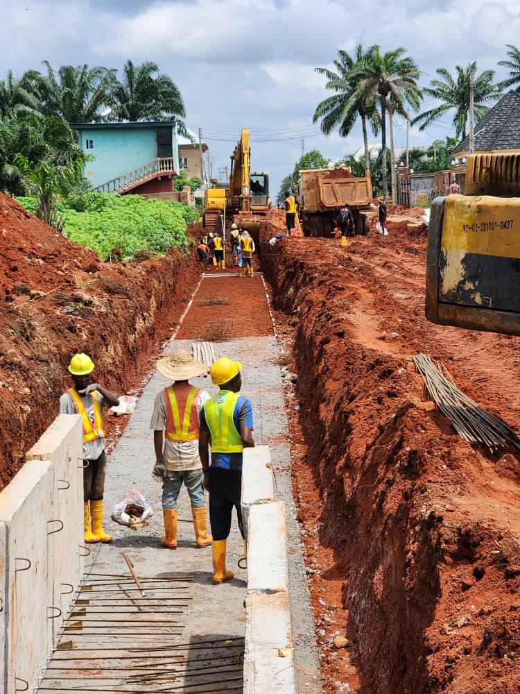
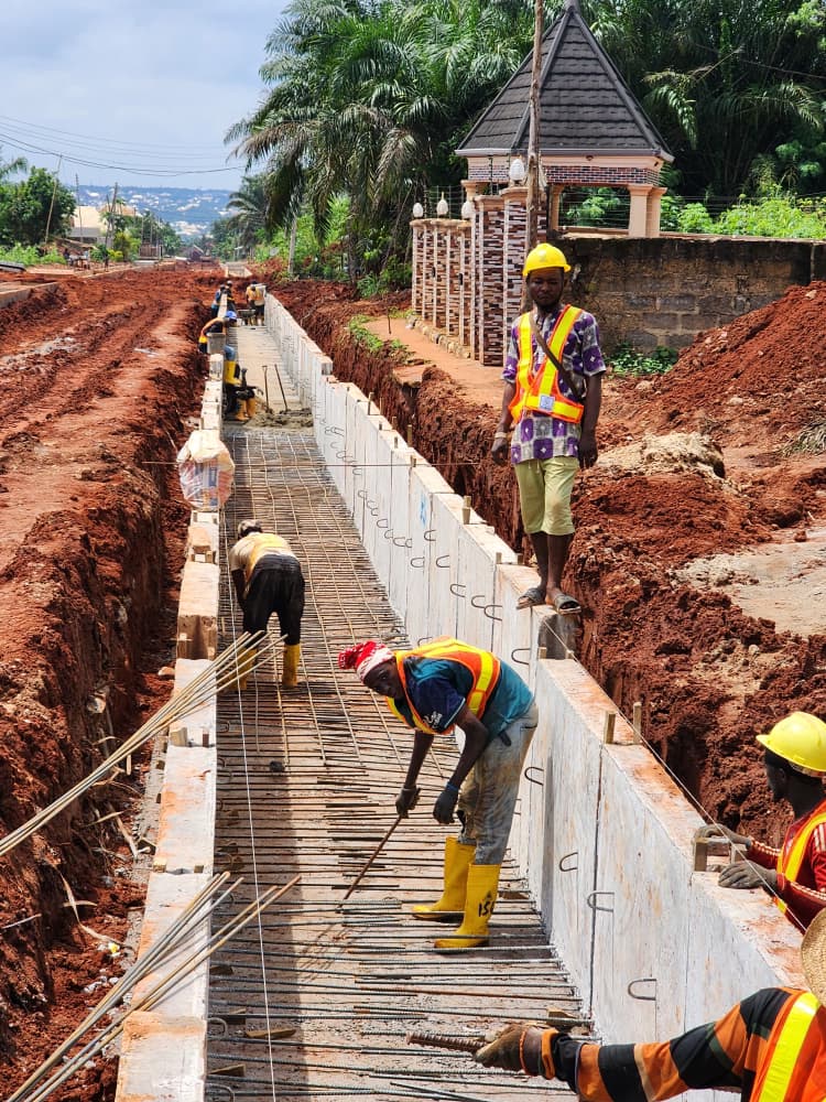
Final Outcomes: Integration of proposed drainage and sewer infrastructure. The images show the installation of precast concrete box culverts and drainage channels along the newly graded subgrade. Rebar detailing and structural preparations for the bridge/culvert elements are visible, aligning with the proposed drainage lines on the survey map.
Based on our hydrological calculations, we specified two primary drain sizes for the corridor. Along most of Obi Road, we constructed a 1.5m wide by 1.2m deep precast concrete drain. However, at specific convergence points, such as CH 1+900 on Enumah Road, the catchment area required a larger capacity, prompting the design of a 1.5m wide by 1.5m deep drain.
The hydraulic capacity of these channels was verified using Manning’s equation for open channel flow:

Where Q is the flow rate, n is Manning’s roughness coefficient (typically 0.013 for smooth concrete), A is the cross-sectional area, R is the hydraulic radius, and S is the longitudinal slope. The 1.5m x 1.5m section on Enumah Road likely required the extra 300mm of depth to accommodate a flatter longitudinal gradient (S) or a larger contributing catchment area (A), ensuring the flow velocity remained sufficient to prevent sediment deposition.
The construction sequence for these drains was methodical. It began with the excavation of the trench, such as the works at CH 2+265 RHS on Obi Road. Once the trench was graded, we poured the concrete blinding (e.g., at CH 2+250 RHS and CH 1+200 LHS). Blinding—usually a 50mm to 75mm layer of lean concrete—is often overlooked, but it provides a clean, level working surface, prevents the structural concrete from losing moisture into the dry laterite, and protects the reinforcement from soil contamination.
Following the blinding, the precast concrete walls were placed. This was particularly challenging at CH 2+350 on Obi Road, where the drain alignment ran directly beside a collapsed section of a residential fence. The precast elements had to be carefully maneuvered and set to ensure structural stability without further undermining the adjacent property. Similarly, precast walls were installed on the LHS at CH 1+400 and along the remaining sections of Enumah Road at CH 1+900.
Finally, the cover slabs were placed, such as the installation at CH 2+075 RHS on Obi Road, transitioning the open channel into a covered box culvert where necessary to allow for vehicular and pedestrian access.
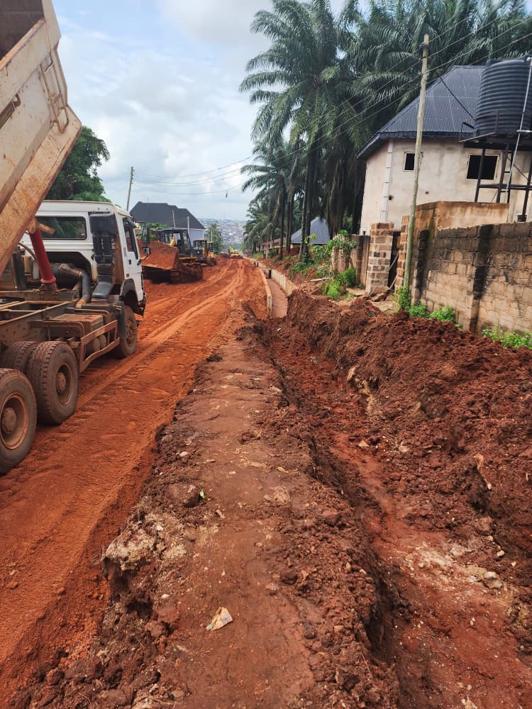
 Longitudinal perspective showing drainage channel construction parallel to road excavation. The elevation differential between proposed road levels and adjacent properties is clearly visible, along with characteristic palm tree-lined corridors. Existing compound walls constrain widening options and necessitate careful transition design.
The Socio-Engineering Reality: Right-of-Way and Community
Technical design is only half the battle in Nigerian infrastructure projects. The other half is navigating the human element.
During the alignment of the drainage on Enumah Road, we encountered physical obstacles—structures and encroachments sitting directly on the proposed Right-of-Way (ROW). The project documentation notes that “compensation was fully settled and work going on to remove the remaining obstacles along our drainage alignment.”
This is a critical aspect of project delivery. No amount of hydraulic modeling will help if the community blocks the excavators. By ensuring that compensation frameworks were agreed upon and settled transparently with the affected residents, the engineering team was able to maintain the design alignment without costly deviations. It is a reminder that civil engineering in urban environments is as much about stakeholder management as it is about concrete and steel.
 Road subgrade preparation demonstrating fill placement operations. The contrast between excavated zones and completed sections illustrates the cut-and-fill process. Background residential structures demonstrate the urban context and the necessity for careful elevation transitions to maintain property access and drainage functionality.
Conclusion
The transformation of Obi and Enumah Roads in Alibiuba Community from eroded, impassable gullies to engineered, graded corridors with robust drainage is a testament to rigorous field engineering. By strictly adhering to the topographical data, managing the geotechnical properties of the lateritic fill, and executing precise structural drainage works, the project has effectively neutralized a severe environmental hazard.
Moving from EGL to PGL in this context wasn’t just about balancing earthworks; it was about reclaiming land, protecting property, and providing the Alibiuba community with infrastructure that can actually withstand the realities of the Delta State climate. Infrastructure development in the Niger Delta demands more than just theoretical design; it requires a willingness to get into the red earth and engineer solutions that hold up against the realities of the environment.
Project Credits
Project: Stormwater Management & Control Measures for Alibiuba Community, Ika South Local Government Area, Delta State.
Client: Delta State Government, Ministry of Works, Illah Road, Asaba, Delta State.
Consultant: JEFCON & Associates Ltd, 11, Engr. John Chiegbuniwe Drive, Off Marian Babangida Way, Phase V Core Area, Asaba, Delta State.
Surveyed By: Surv. Justice U. Anyin
Checked By: Engr. J.C. Onwualu
Approved By: Ministry of Works, Delta State.
References